
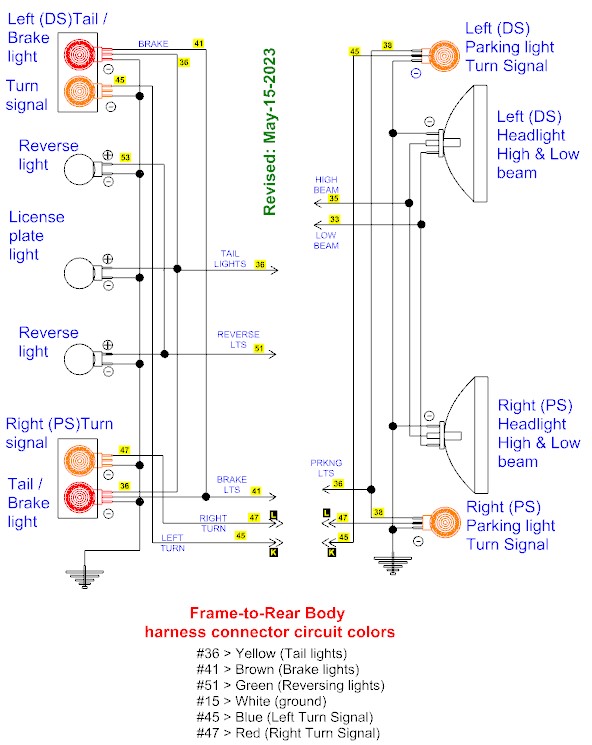
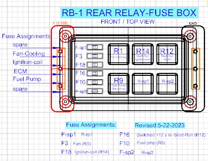
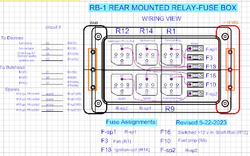
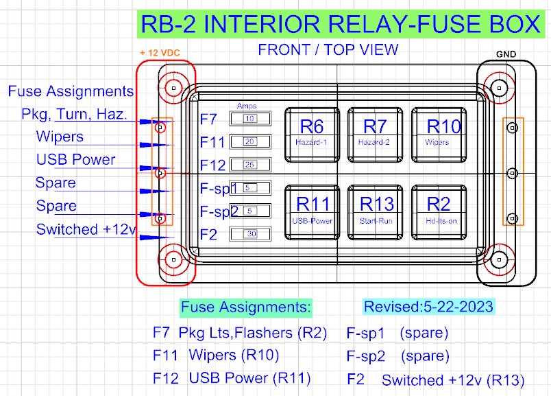
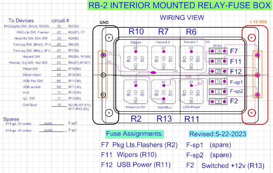
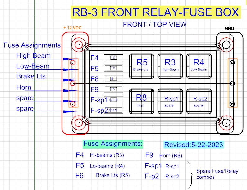
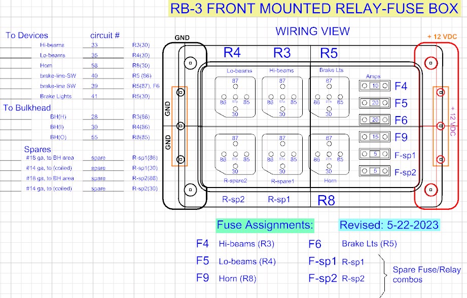
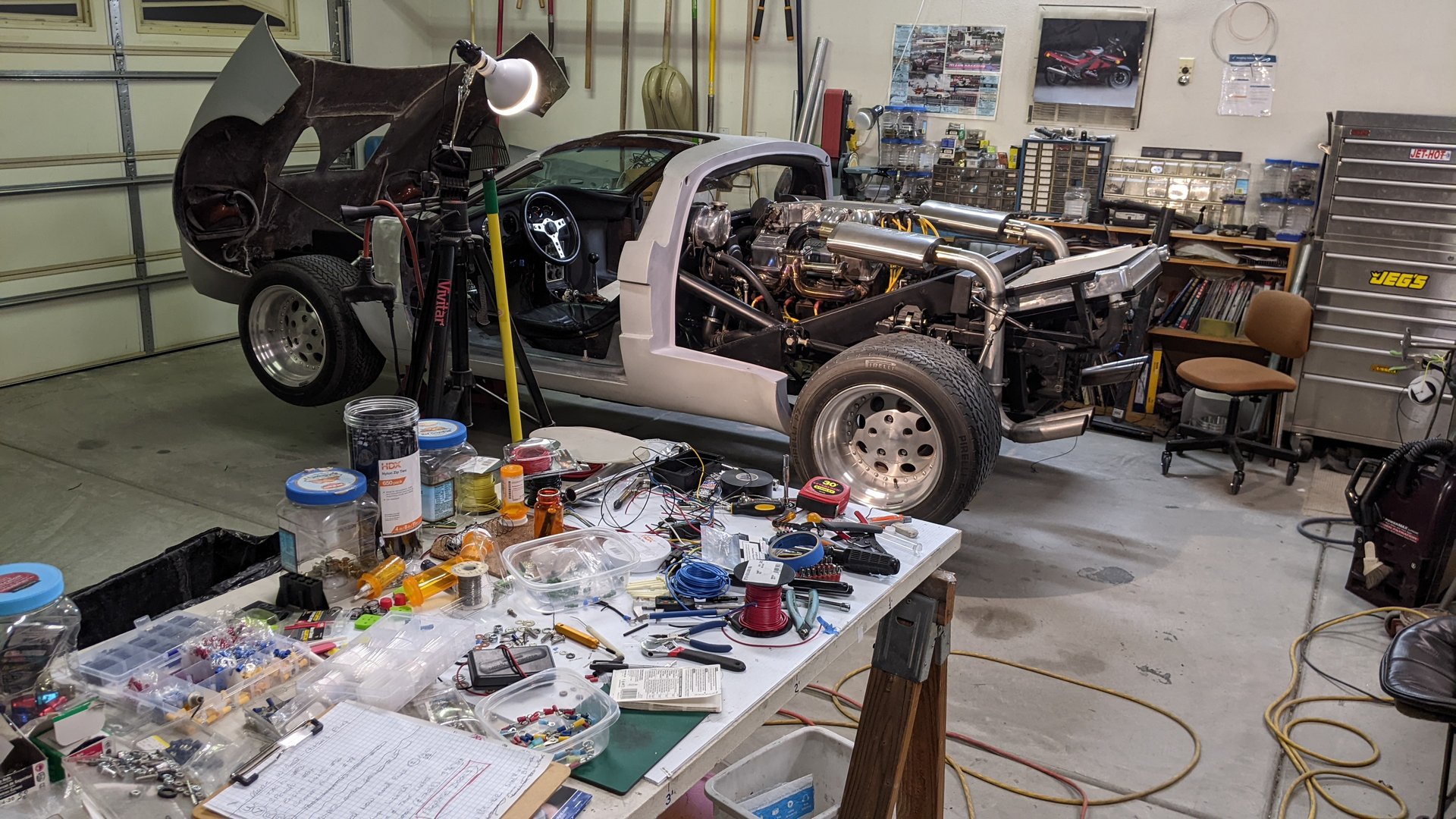
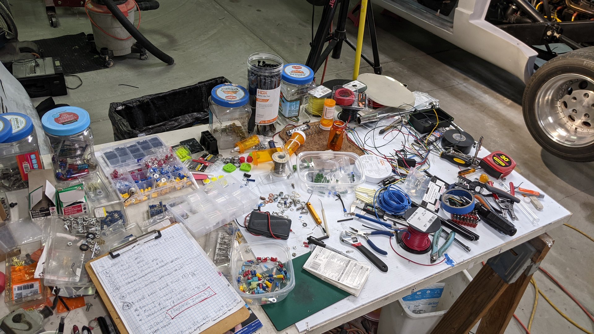
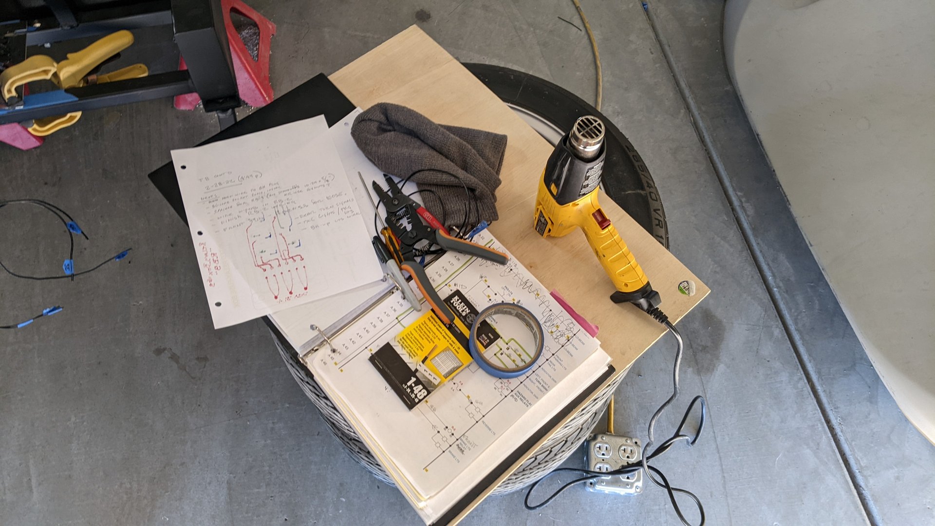
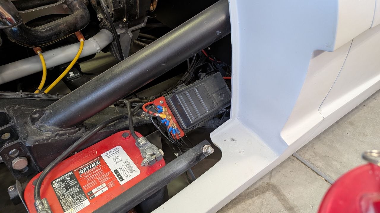
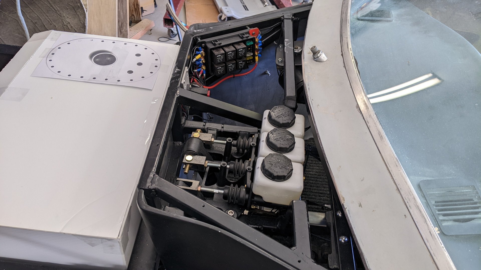
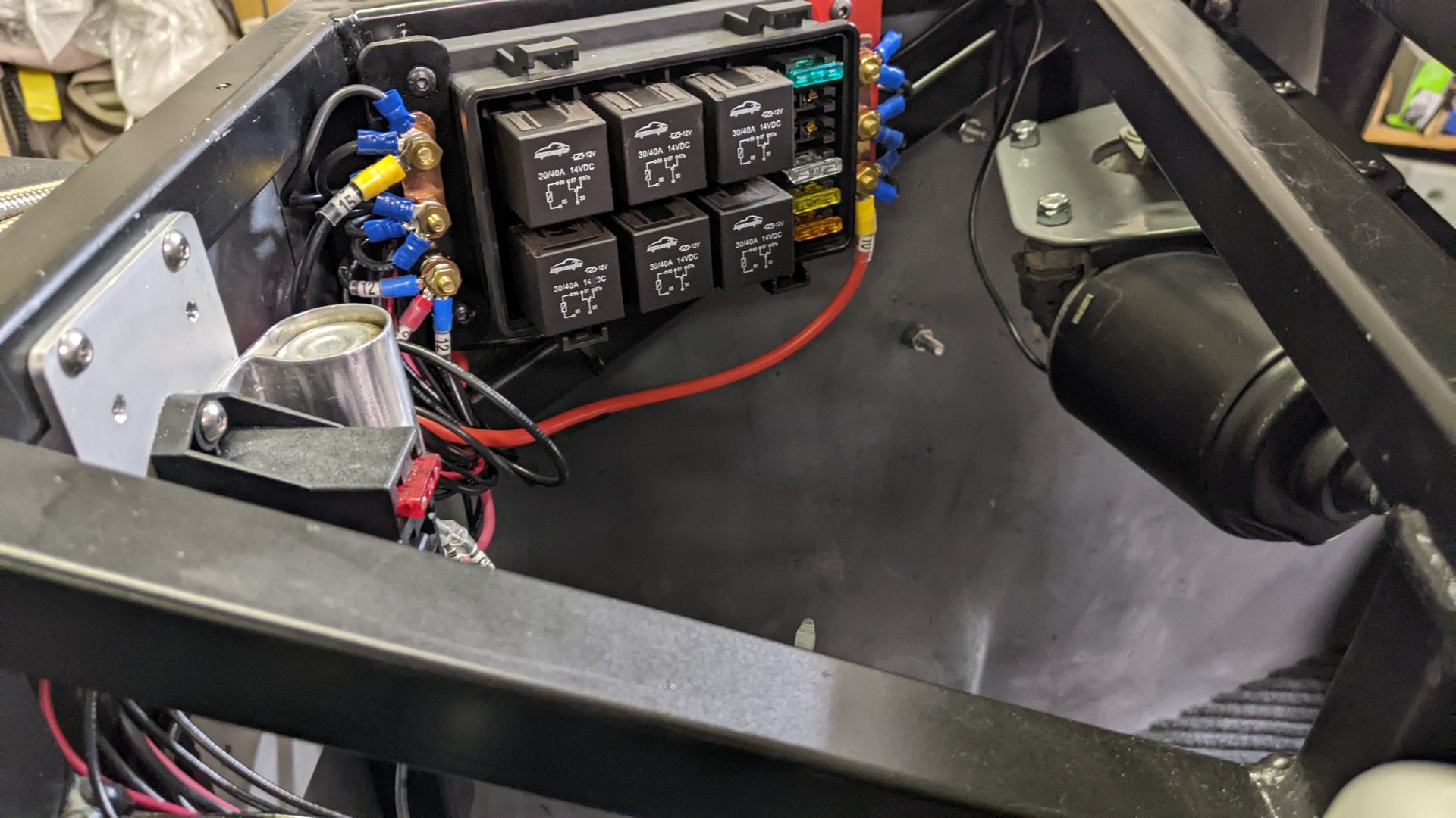
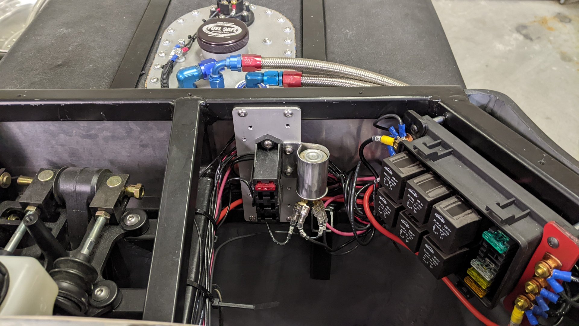
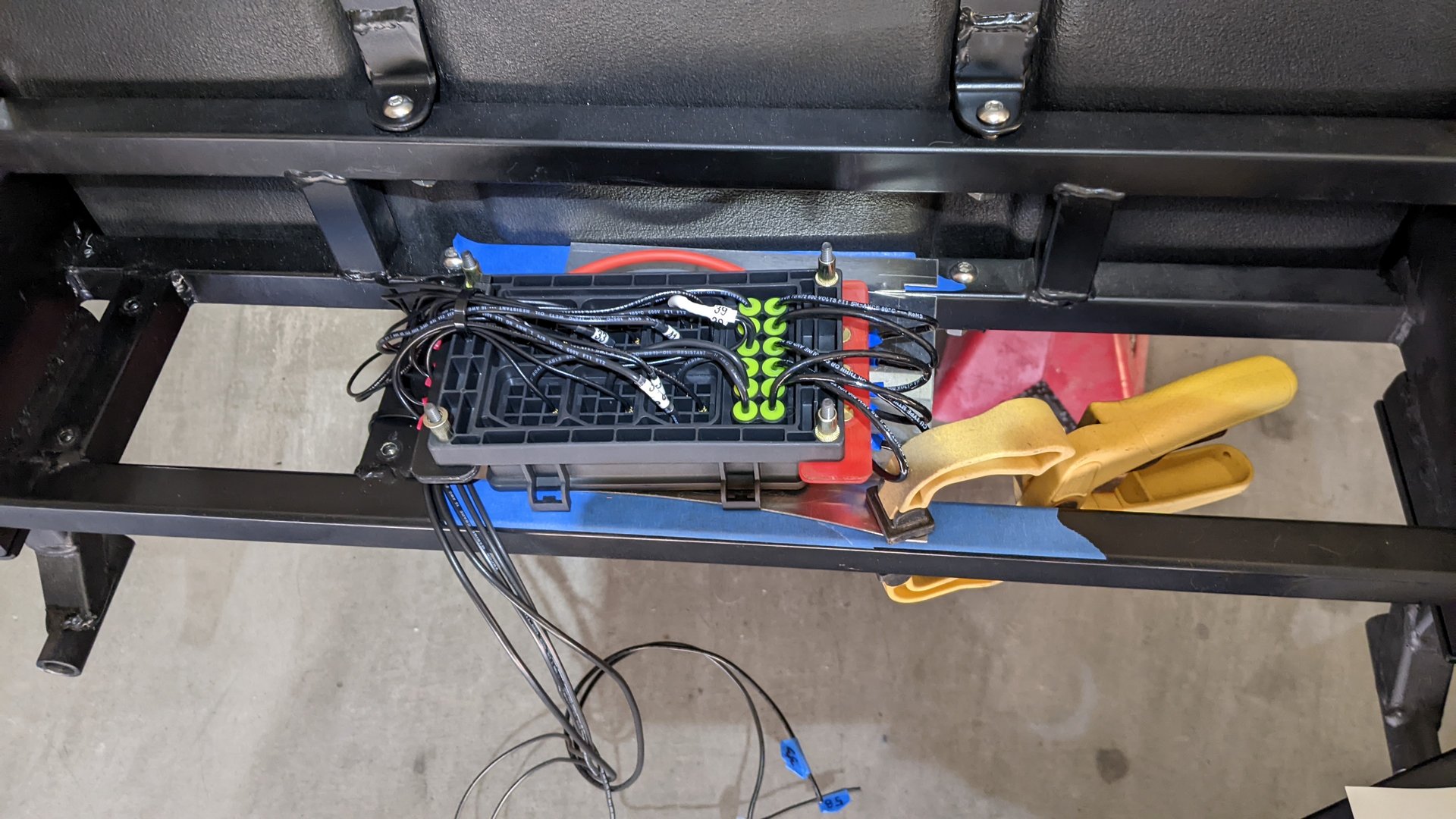
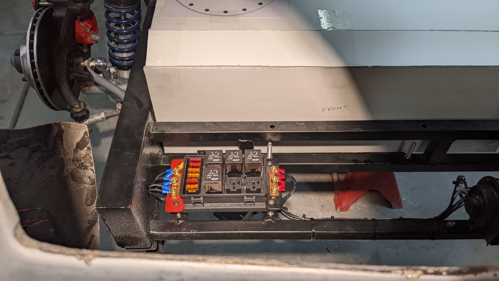
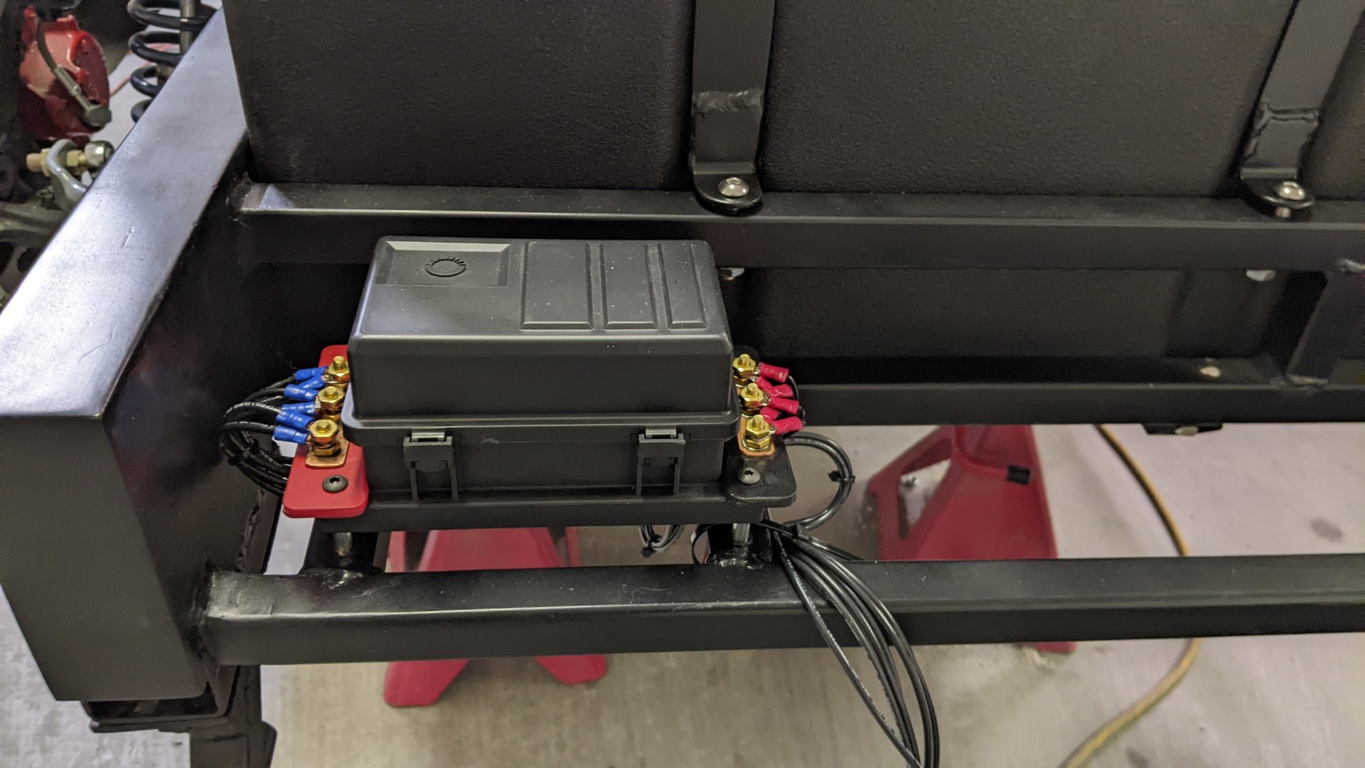
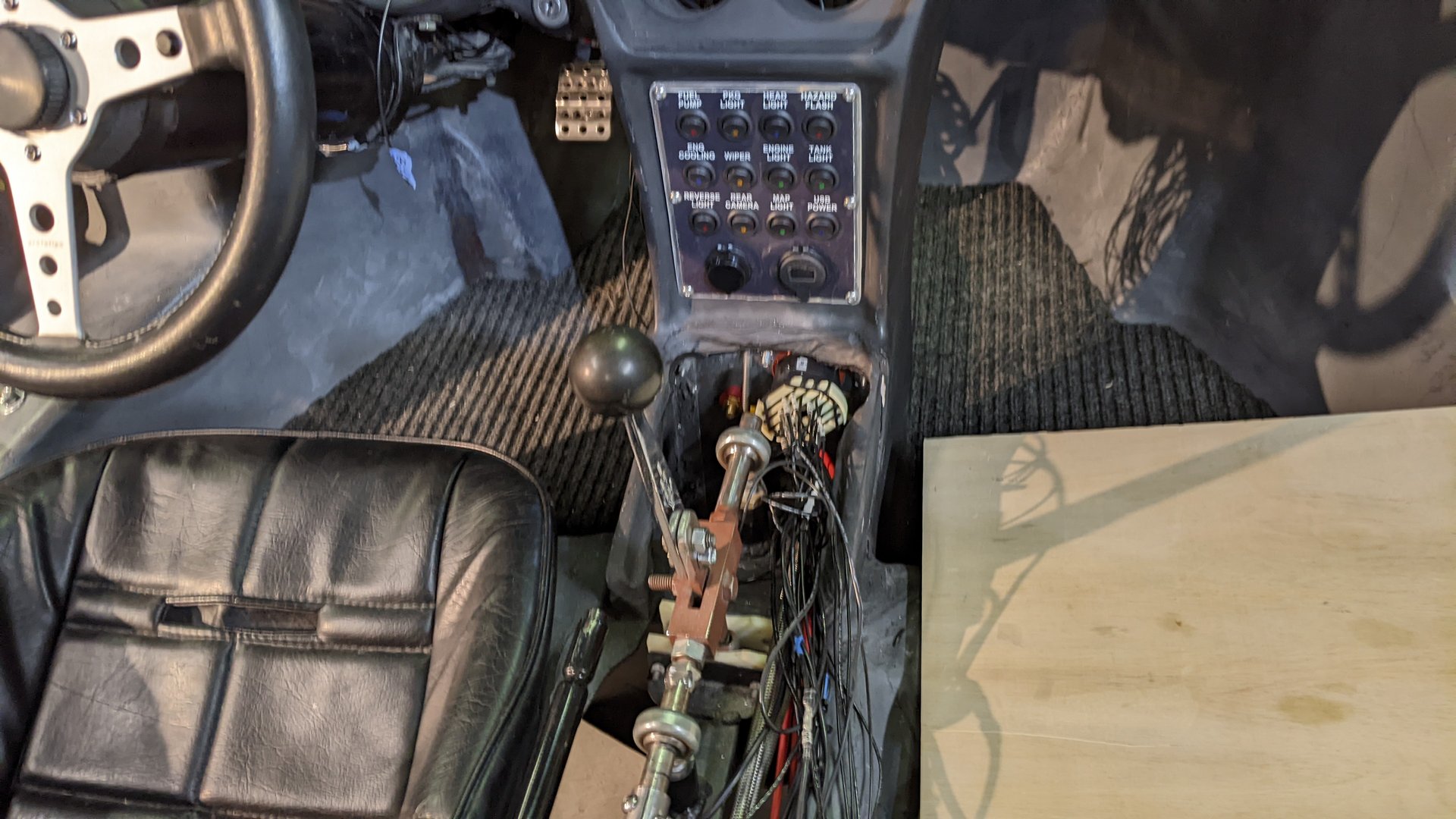
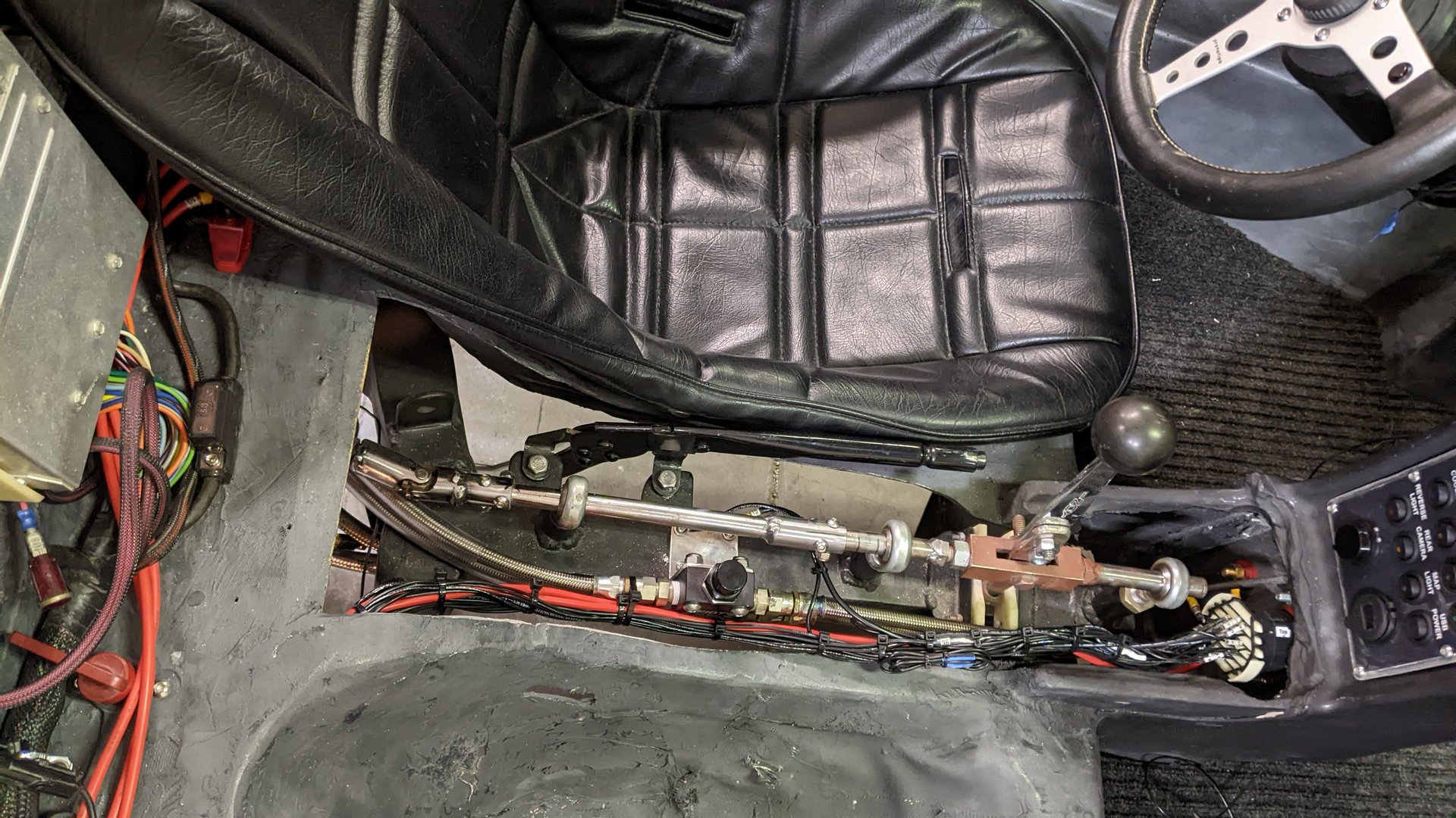
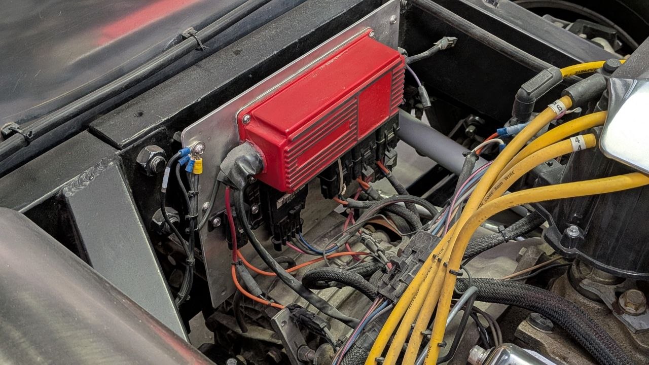
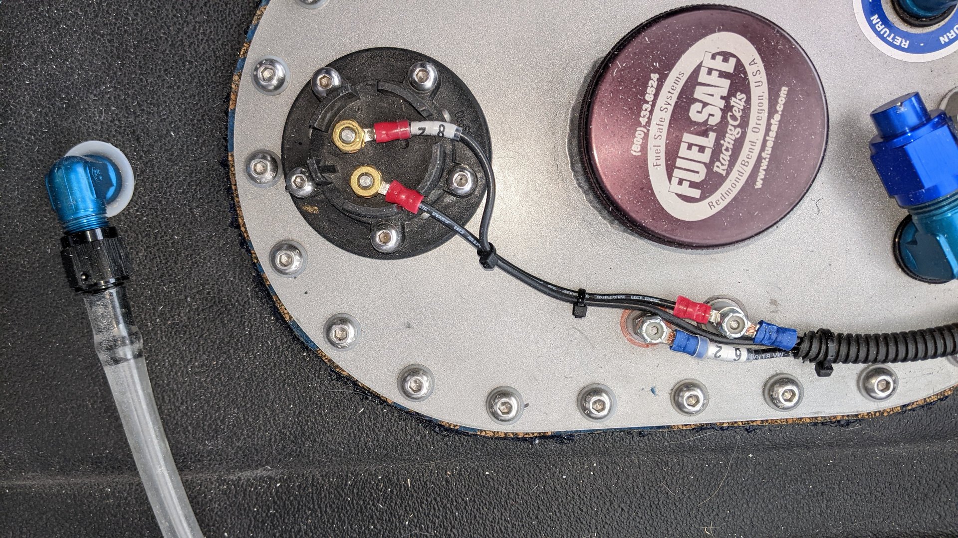
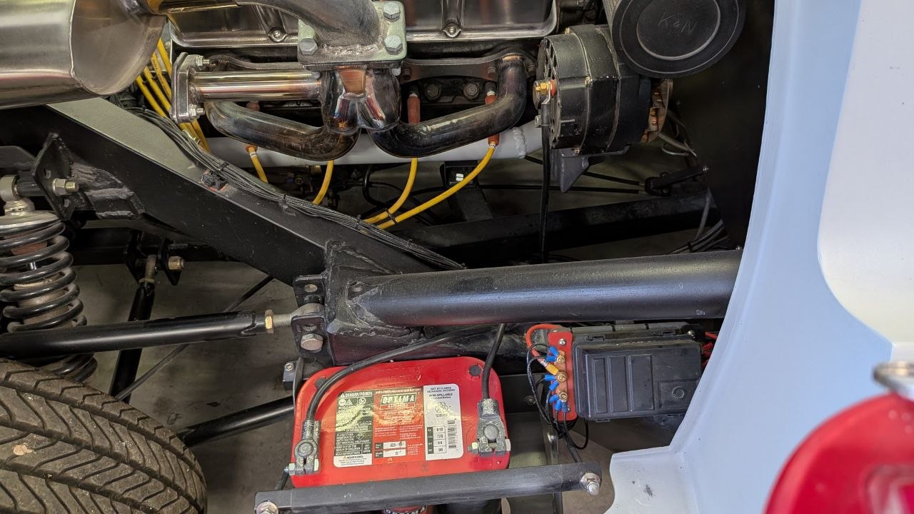
For several reasons, I decided to create circuit drawings in CAD and re-wire the car myself instead of using an available hot rod wiring harness kit. I had quite a number of years of experience working in a company that specialized in designing and building industrial control systems and I had specific ideas in mind for where I wanted to place fuse and relay boxes. Also, I assumed that the commercially available wiring kits were intended for the typical front-engine car or truck layout, not a mid-engine kit car.
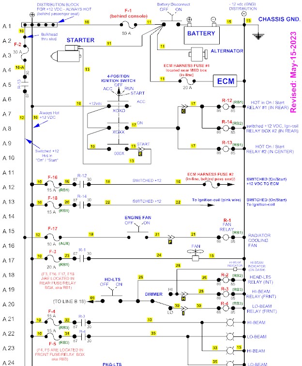
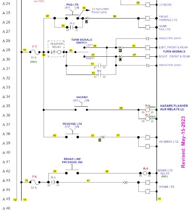
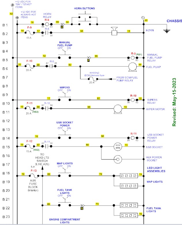
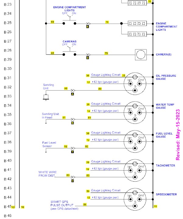
My main circuit drawings are in what is called “ladder diagram” format, which was/is common in the industrial controls field. On my drawings, shown below, the vertical line on the left side of the ladder is connected to the positive side of 12 volts, and the vertical line on the right side of the ladder is generally connected to chassis-ground or the minus side of the 12 volt power.
Disclaimer: The images and drawings displayed on this website represent how I designed and/or implemented the construction of my car. I am a car hobbyist, not a professional automotive engineer and I am not representing that any images or text on this website are the best or correct way to do anything. The content on this website is only for thought provoking and entertainment purposes. I am not responsible for anything resulting after someone views this content. Enjoy the story.
Next: Converting the old mechanical Stewart-Warner speedometer to GPS-stepper motor
Back to the Content Links for this post.


