
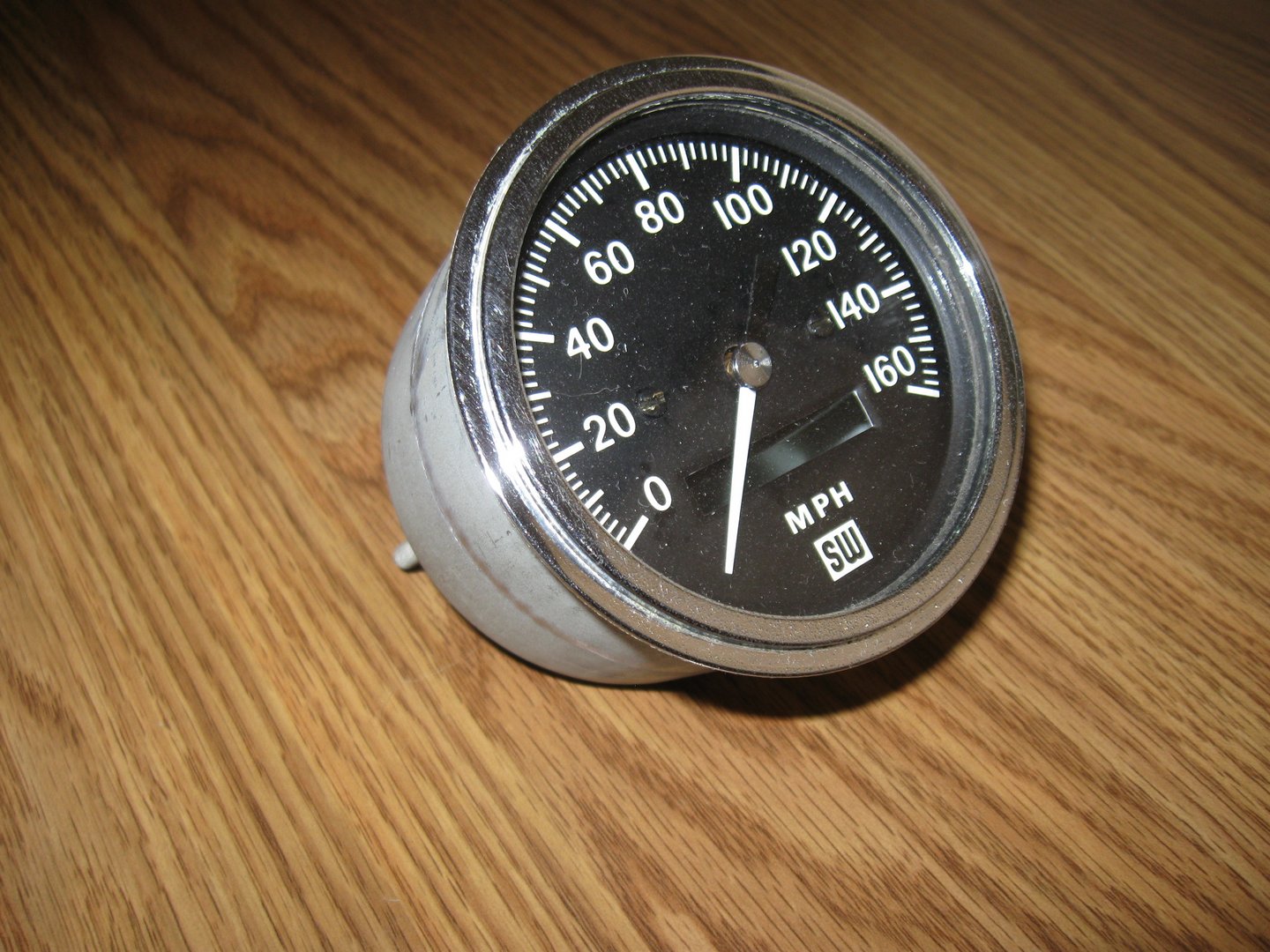
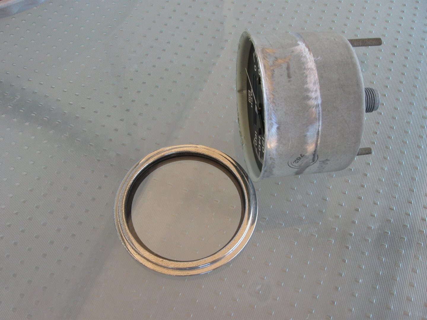
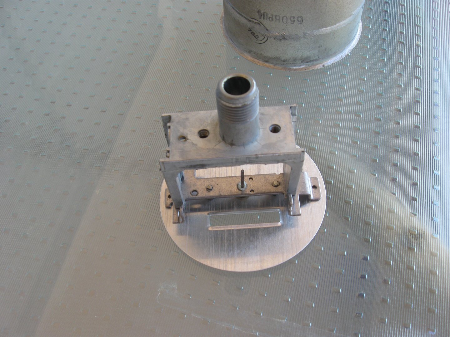
After viewing this page, you might agree it would be more accurate to title it, “Creating a Digital/Analog GPS Speedometer From Scratch“. The only parts I ended up using from the original Stewart-Warner unit are the chrome bezel, glass window, and the metal case.
Back in 1976, when I first assembled this Valkyrie, I installed a nice new Stewart-Warner mechanical speedometer in the dash next to a Sun brand tachometer with a matching black and chrome style. They looked great together, but I never got around to getting a long speedometer cable and figuring out how to make the German built ZF transaxle work with the American made Stewart-Warner speedometer. It was one of those details I kept putting off because there were so many more important issues that needed solving. Thirty-five years later, during the second major rebuild, I decided I really needed a working speedometer. I also noticed that electronic speedometers, having been used by OEMs for years in new cars, were becoming popular in the aftermarket.
I was up for the challenge
My thinking was, an electronic speedo could pick up pulses from a hall-effect sensor mounted near the output shaft flange of the ZF transaxle and I wouldn’t have to be concerned with adapting long mechanical speedometer cables and figuring out gear ratios, and all that stuff. After seeing how relatively expensive new electronic speedometers were at the time, I got the great idea that I was going to figure out how to convert my existing SW speedo unit to work with a stepper motor. Many years earlier, I had done some programming of microcomputers in the industrial control environment, and this sounded like it could be a fun project, even though I already had numerous other tasks to complete related the the Valkyrie restoration.
Time was running out. I needed a working speedometer.
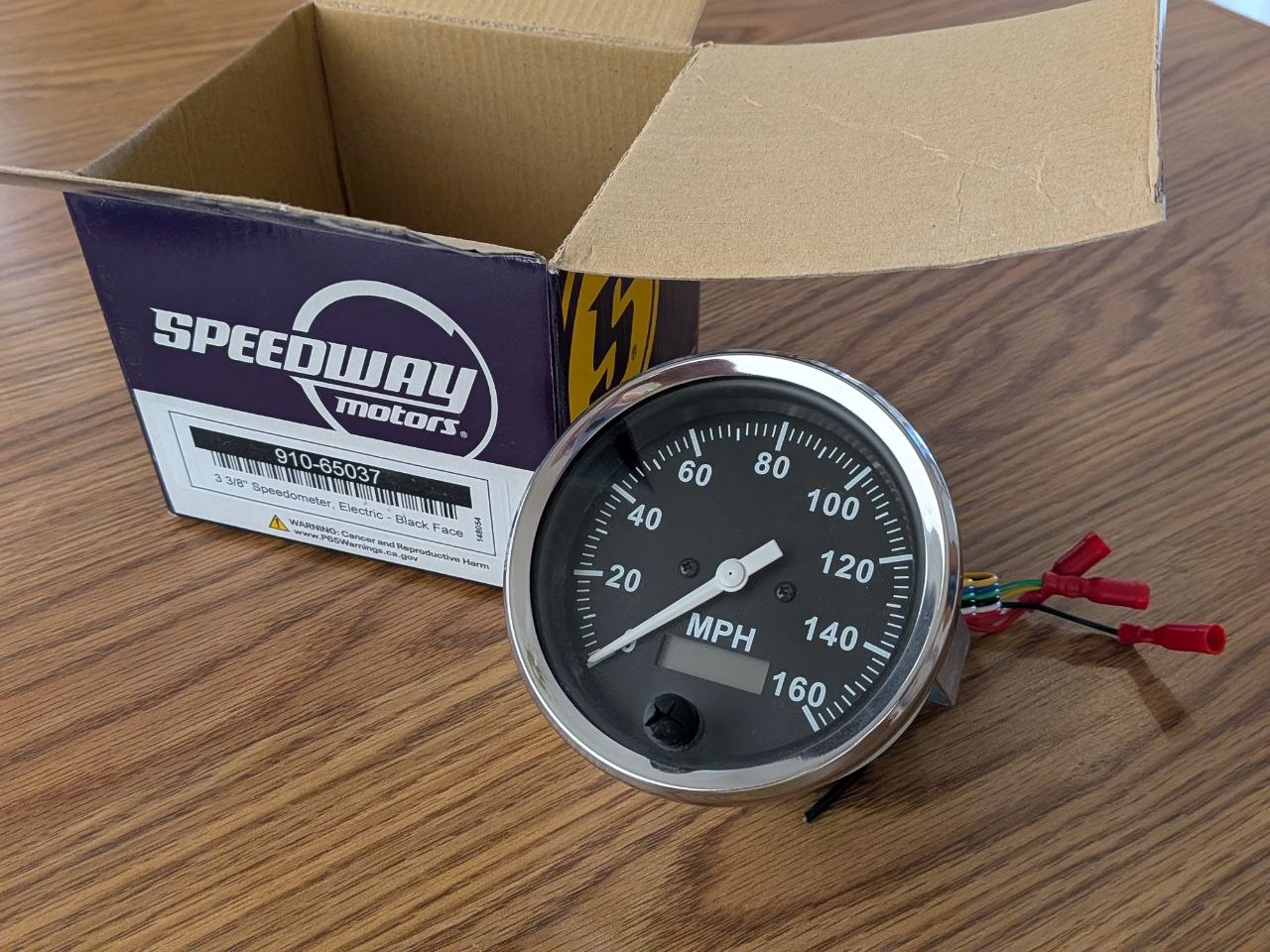
This somewhat impractical idea turned into quite a long, drawn out sub-project that I nearly gave up on when the second major rebuild was nearing completion and the electronic conversion project still had a ways to go. I needed to have a working speedometer filling that hole in the dashboard when I took the Valkyrie for the required DOT-Safety inspection. So, I purchased an electronic speedo unit from Speedway Motors that configurable. It was advertised as accepting a range of pulses-per-mile. After fiddling with this for several weeks trying to make it work reliably, I still did not having a dependable speedometer that recorded mileage and didn’t self-erase. It seemed to work OK during bench testing, but was very erratic when mounted in the car with the engine was running. I did not have an oscilloscope to look at the signal going into the speedometer, but I suspect it was picking up a fair amount of noise from the ignition system. So, with the Speedway Motors speedometer having a very jumpy speed pointer and a hard-to-read odometer display that would not retain the accumulated miles, I revived my GPS-stepper-motor speedometer project with come confidence that I could make a better unit.
Dust off the speedometer project, again
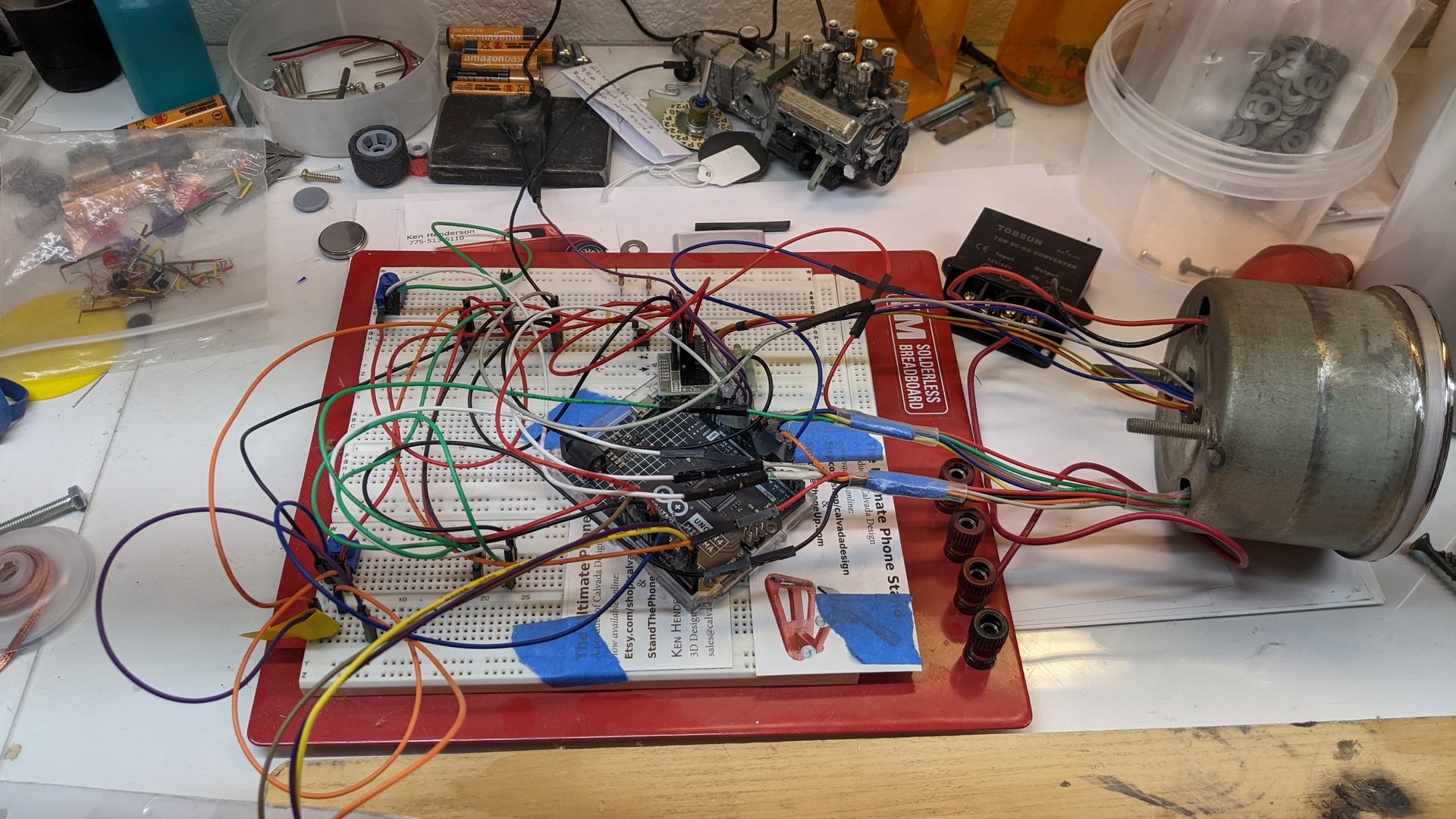
The initial plan for my electronic speedo was to count pulses using a hall-effect sensor mounted near the passenger-side half-shaft adapter on the transaxle. Shielded cable would carry the pulse signal from transaxle area to the speedometer. Each pulse received represented a distance that could easily be converted to a speed when integrated with time. I was making some progress with the software but the Arduino Uno I was using seemed to be struggling to keep up with all of the floating point calculations that were needed. It had to calculate the speed, determine the correct position for the pointer, plus keep track of the accumulated distance, which needed to be periodically written to EEPROM.
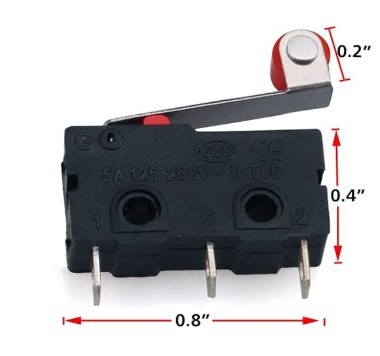
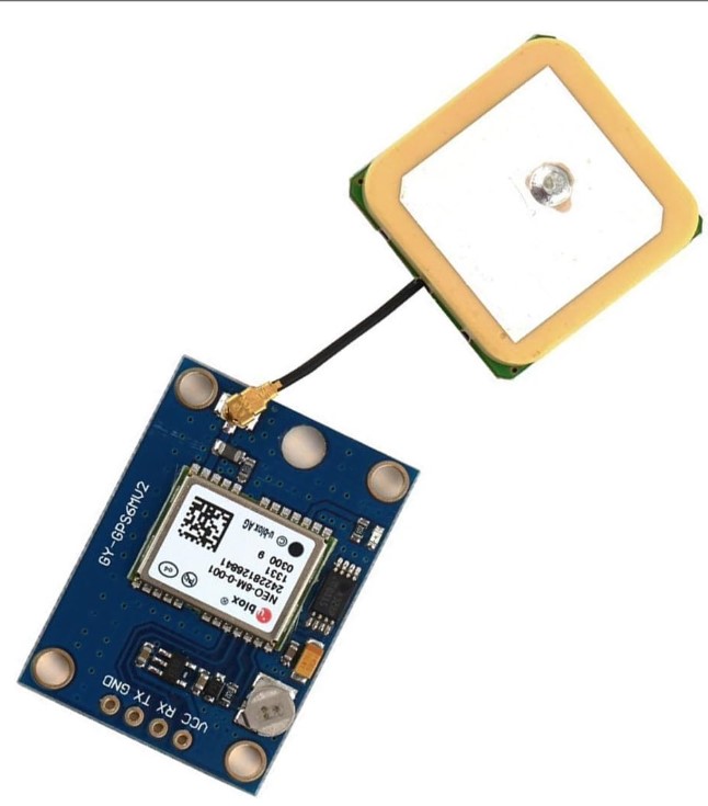
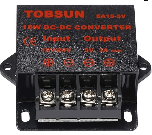
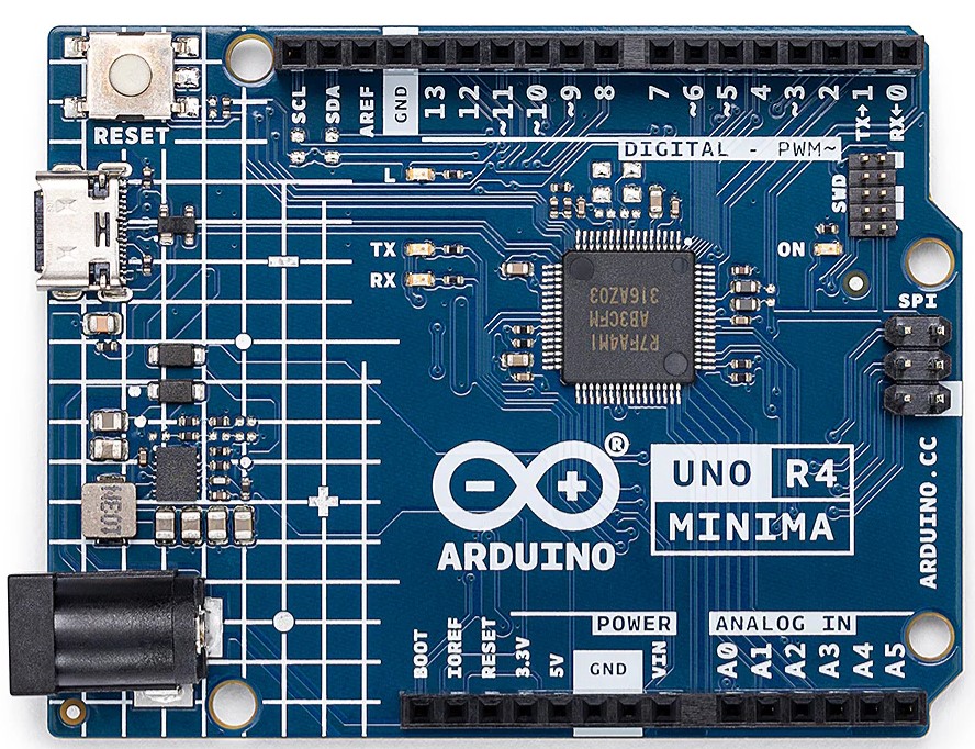
A simpler method
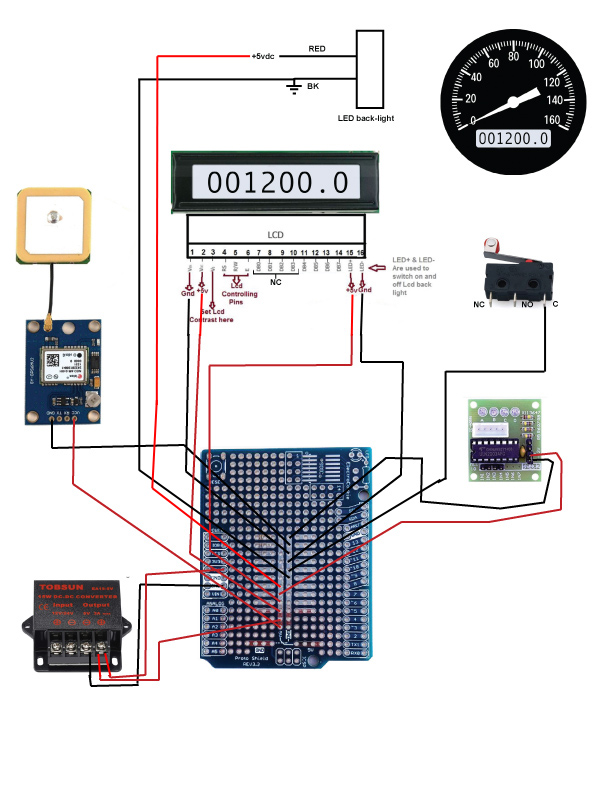
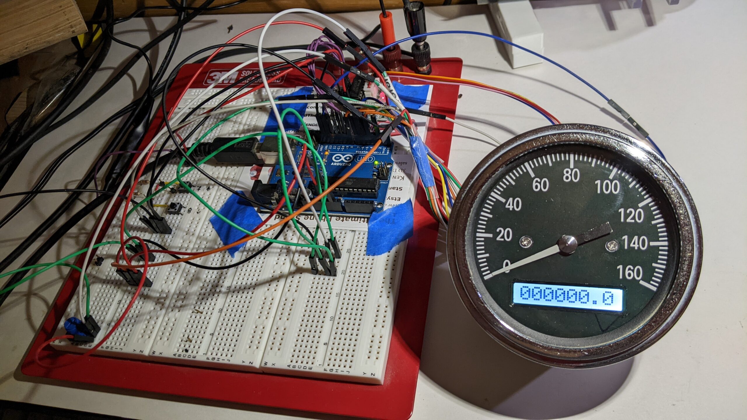
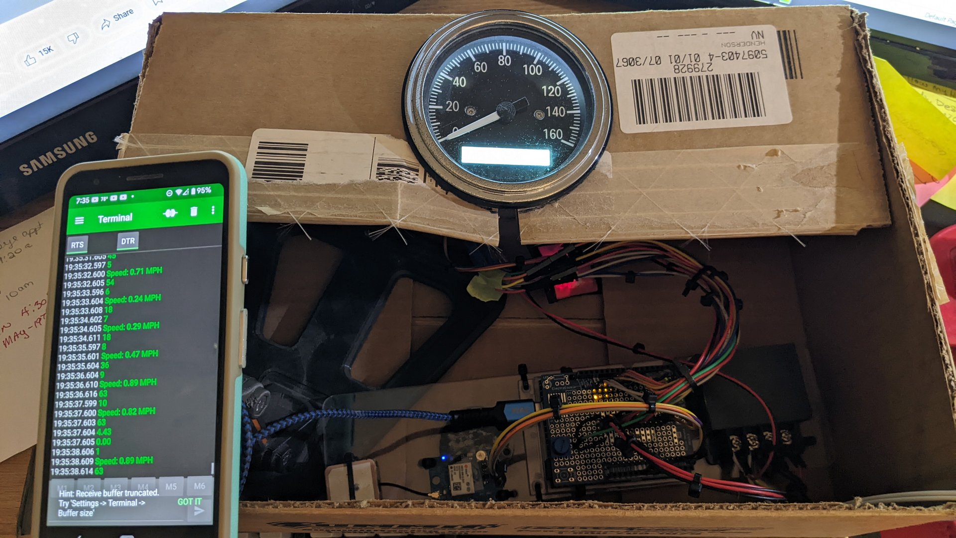
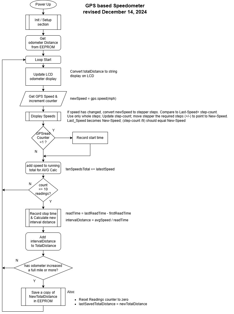
At some point I realized I could drastically simplify the coding by using a GPS module that has, as one of its available outputs, the actual speed in miles per hour. Suddenly the software was much simpler. The need for floating point math was nearly eliminated.
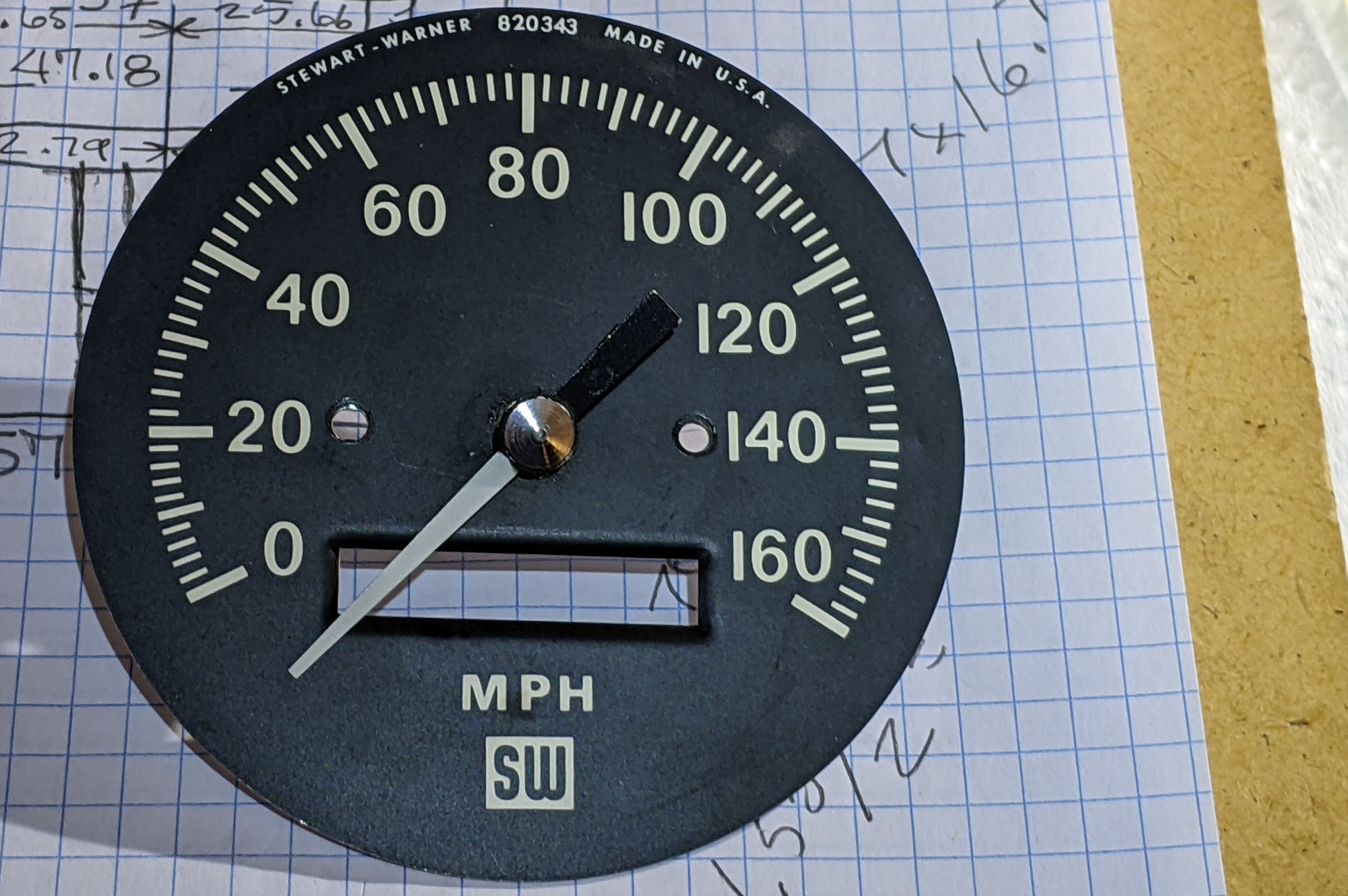
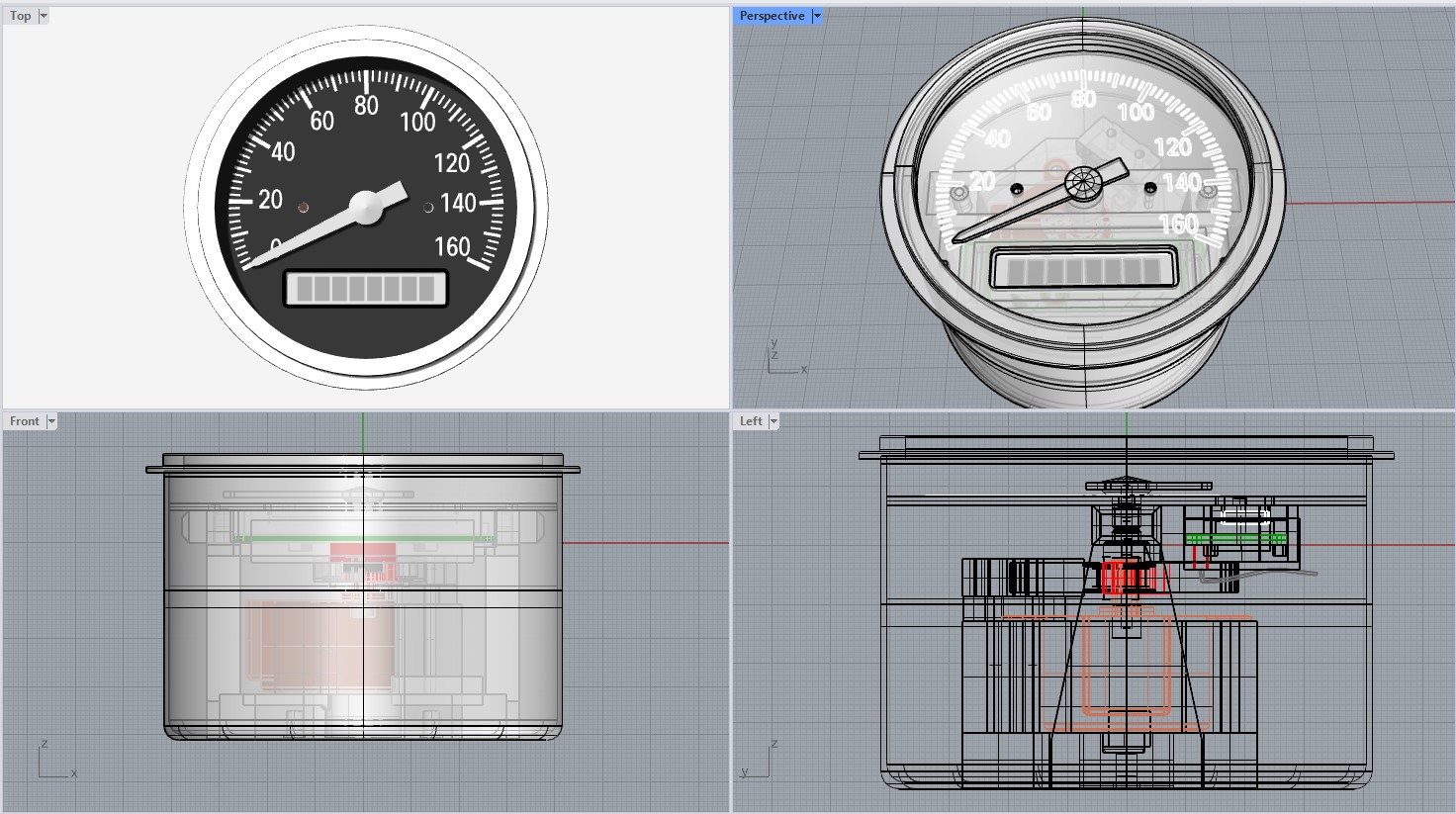
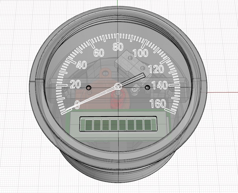
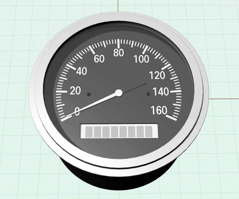
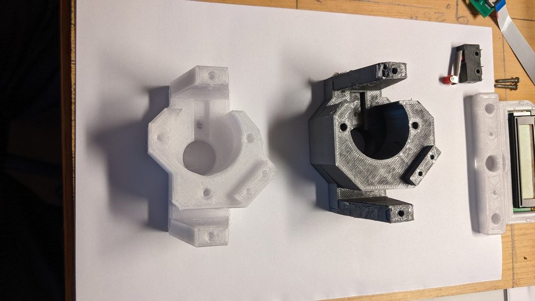
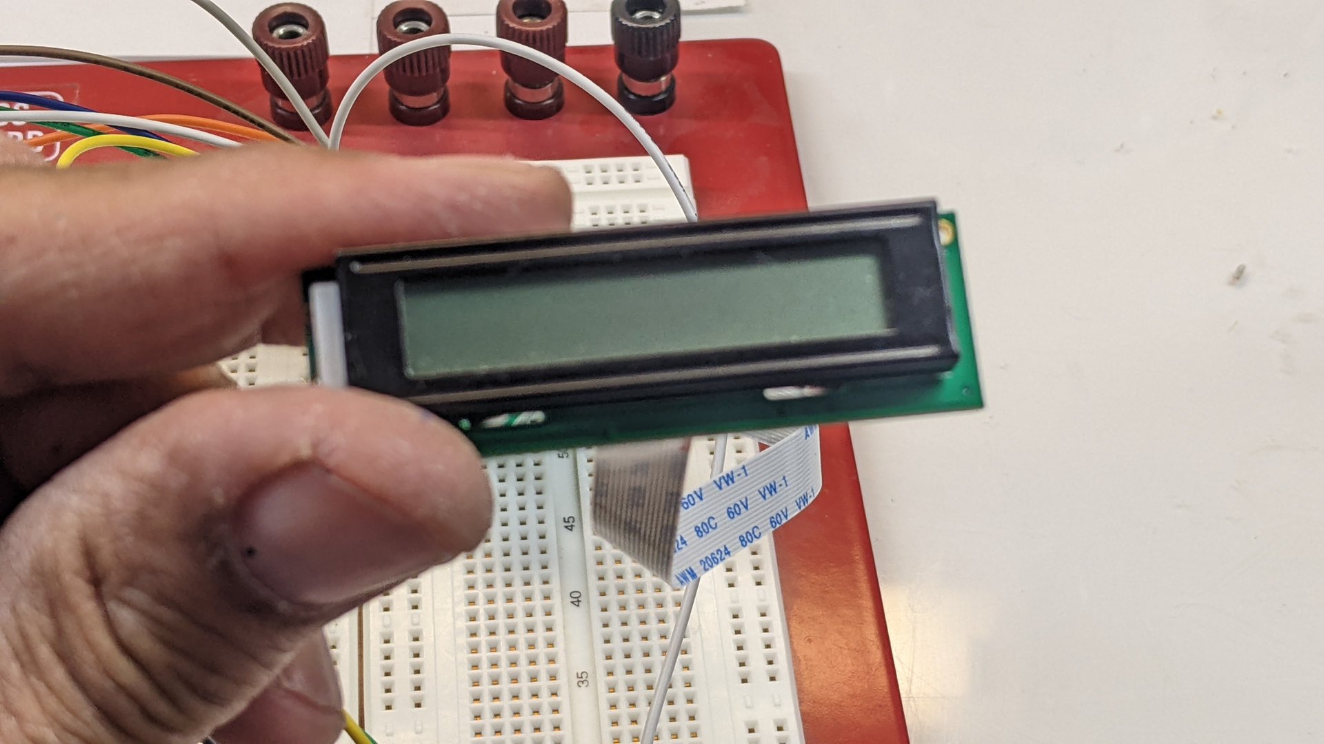
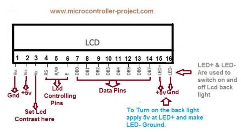
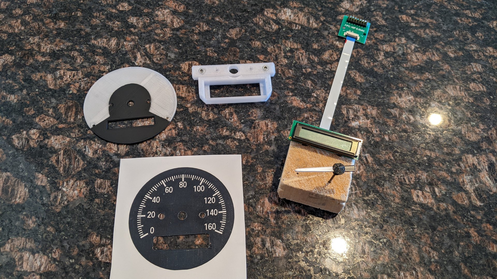
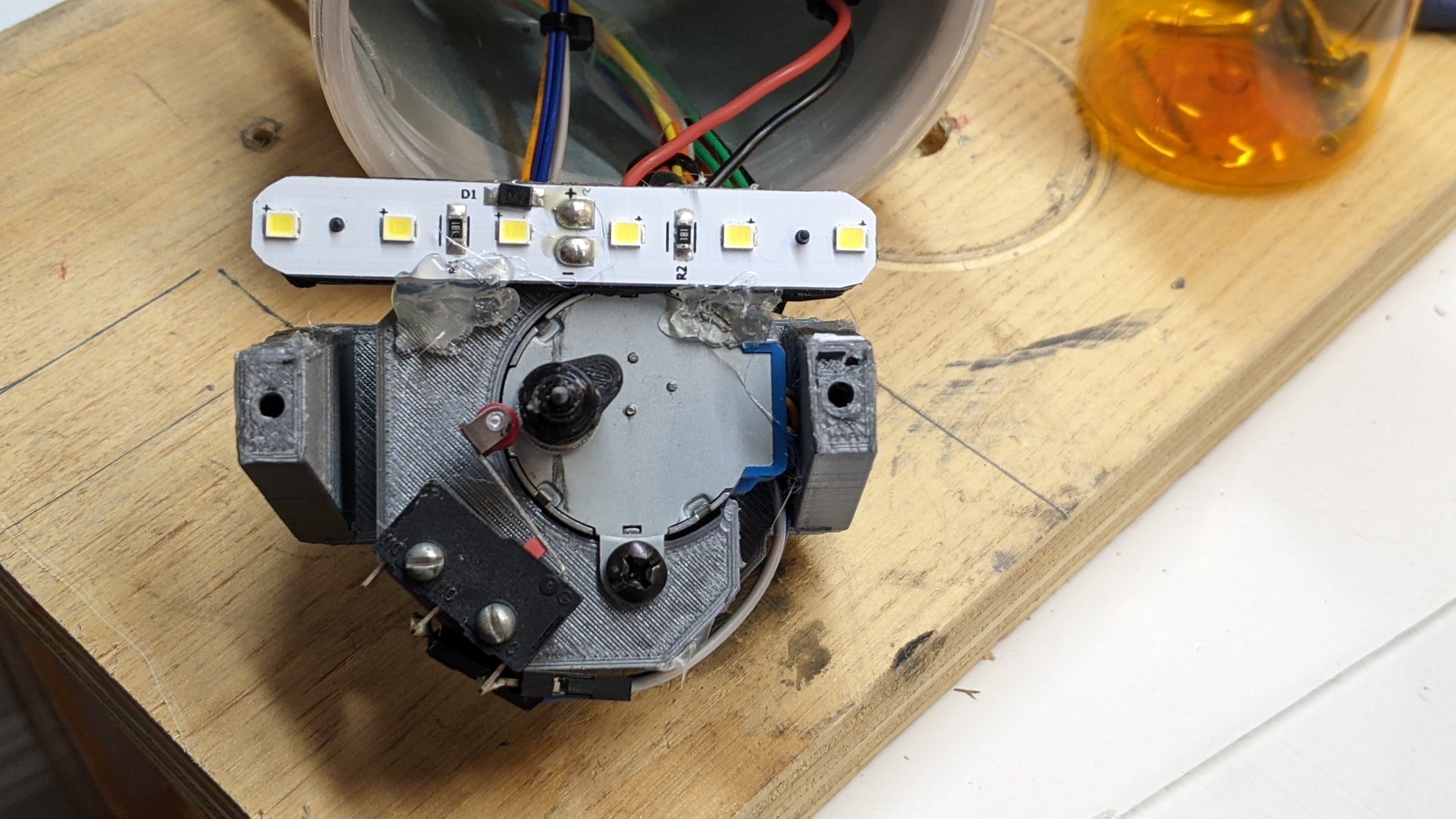
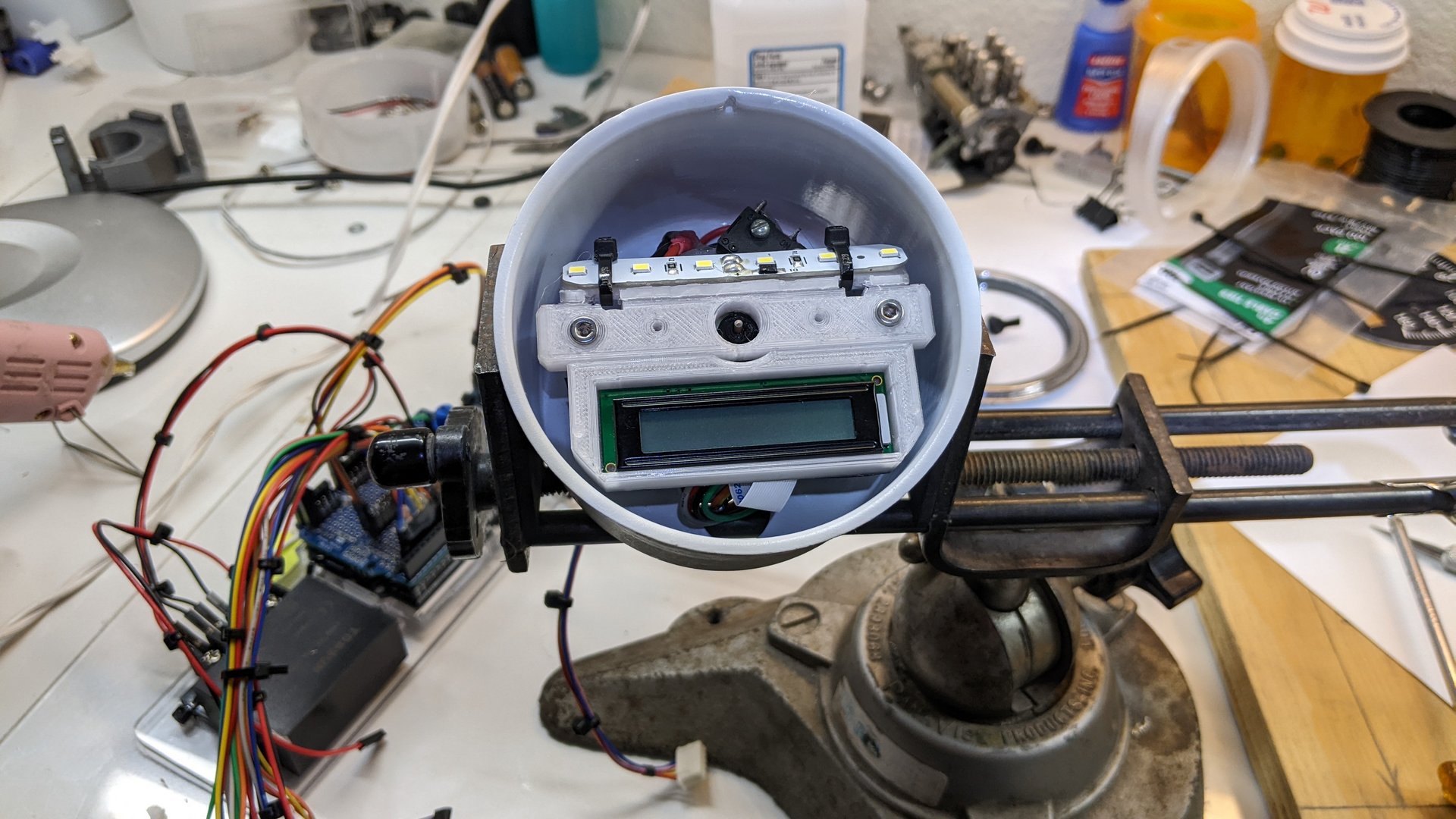
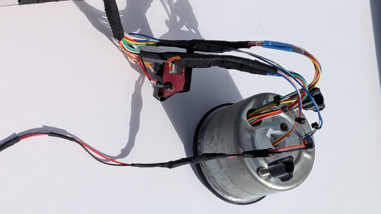
The other challenge was packaging. I needed to find a suitable LCD unit for the odometer display, plus mount a stepper motor with a pointer. After I found a single-line LCD that would fit in the case, it then became clear that the old Stewart-Warner gauge face had a too small window for the LCD, and it was in the wrong place. I would need to make a new face for the gauge.
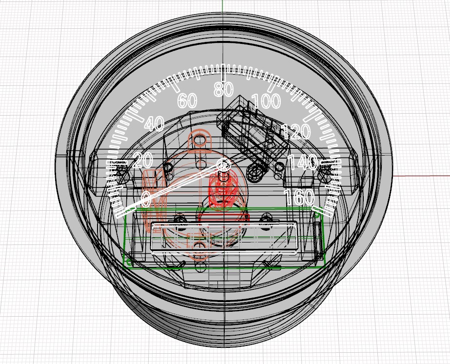
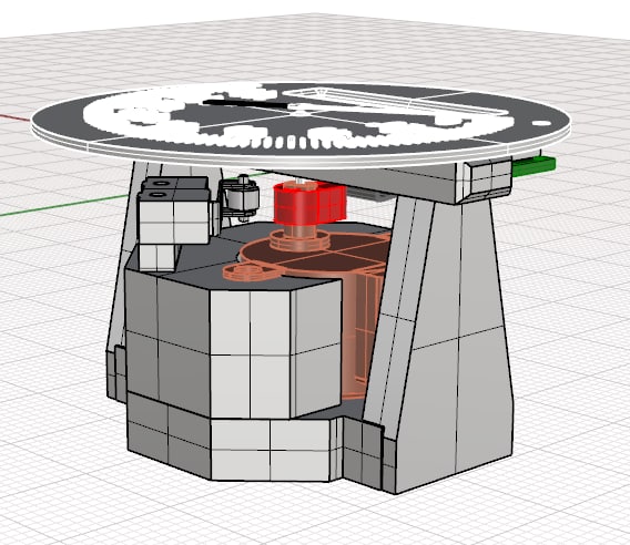
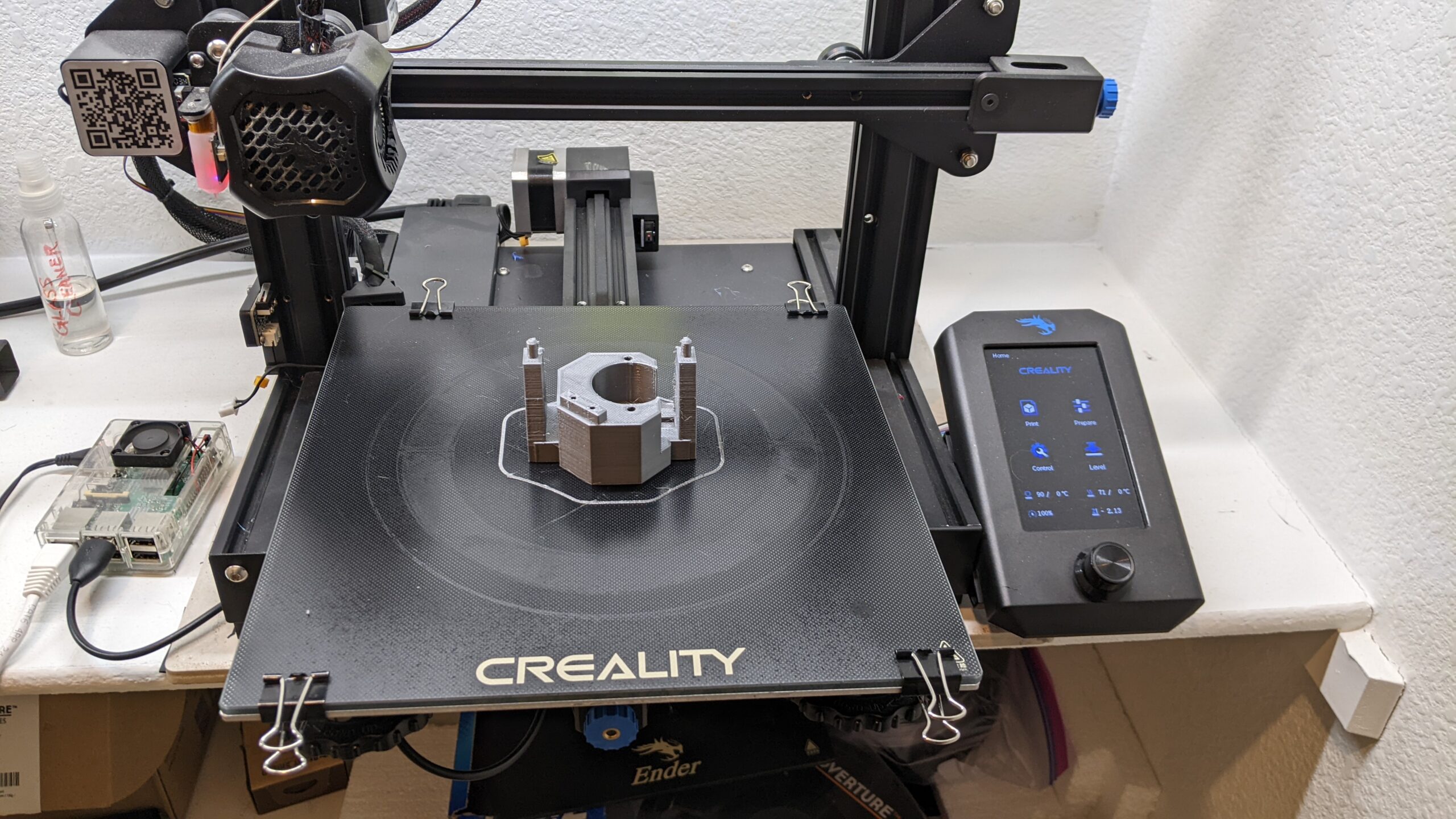
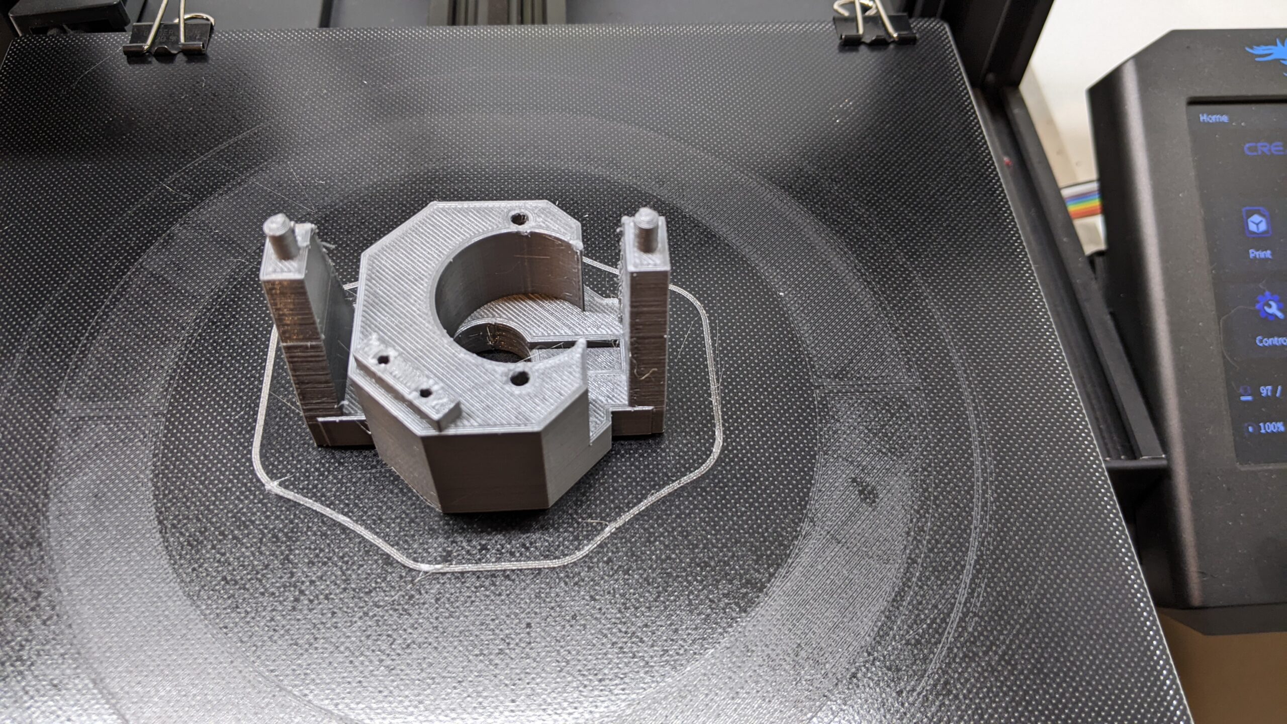
CAD and 3D printing made all of this feasible, and a little help from ChatGPT with the coding got this project over the finish line, but it all took time. Each physical component was carefully measured and a 3D model of the part created. All of the parts were then assembled virtually in CAD, where possible interference was checked by viewing the model from many angles.
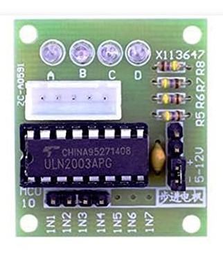
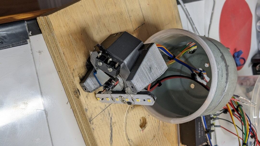
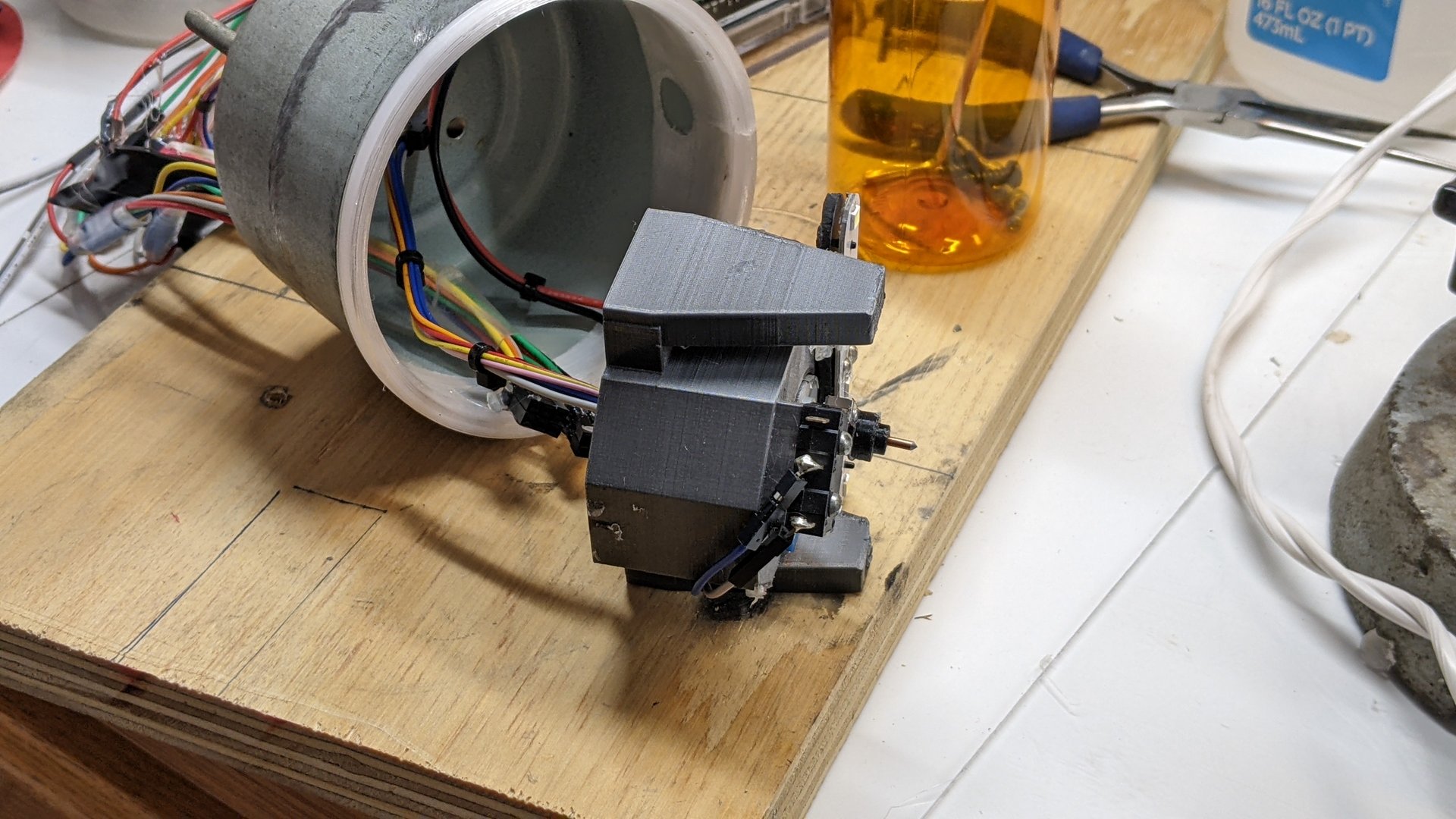
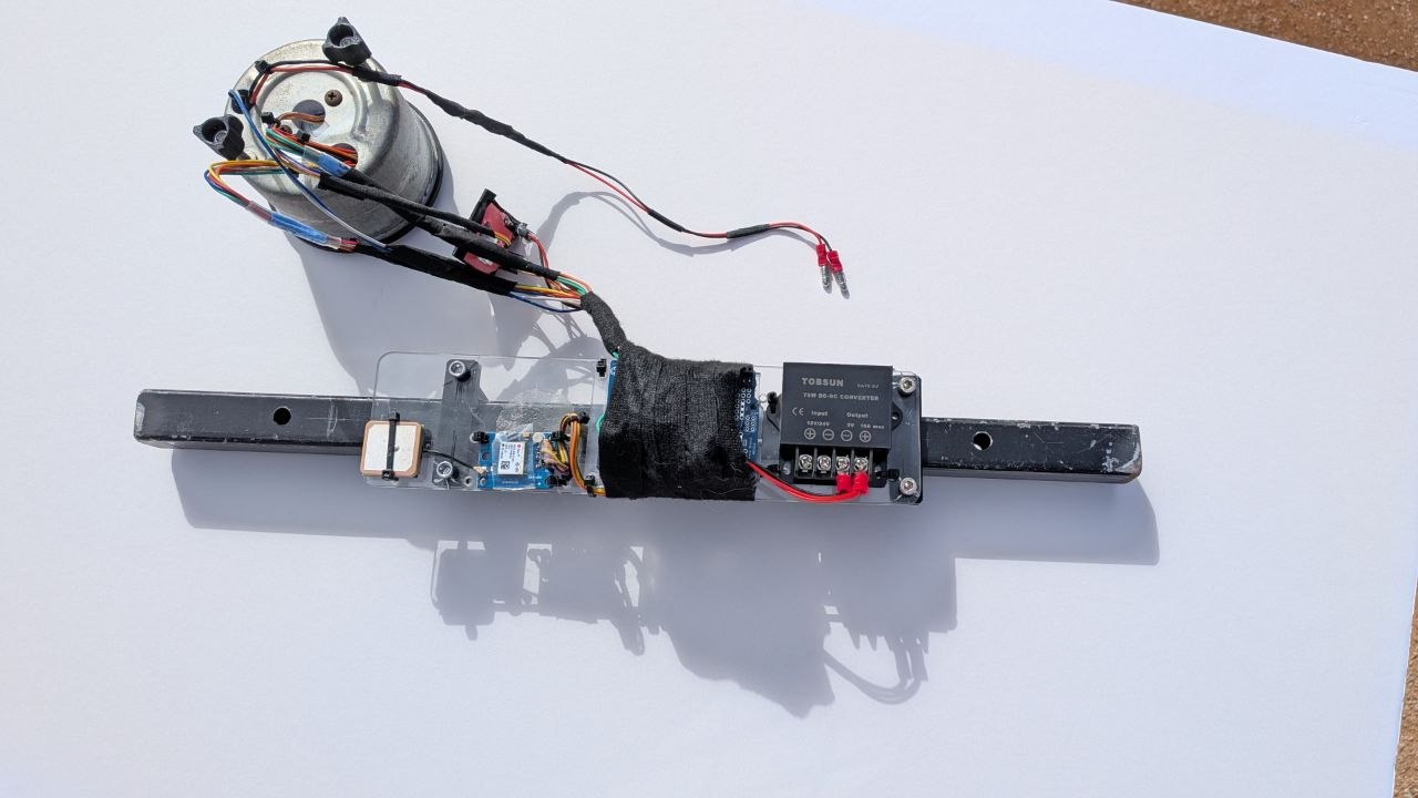
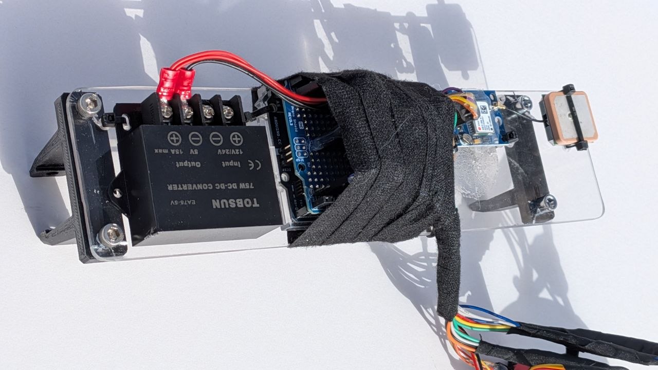
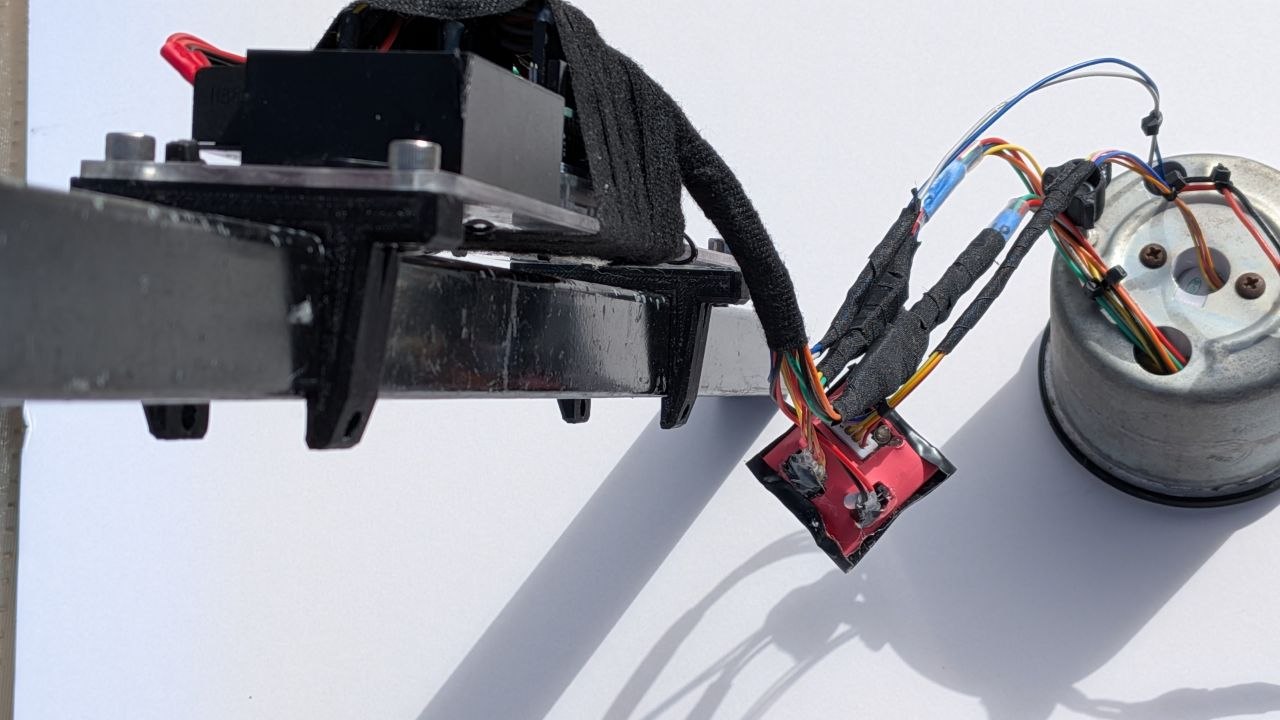
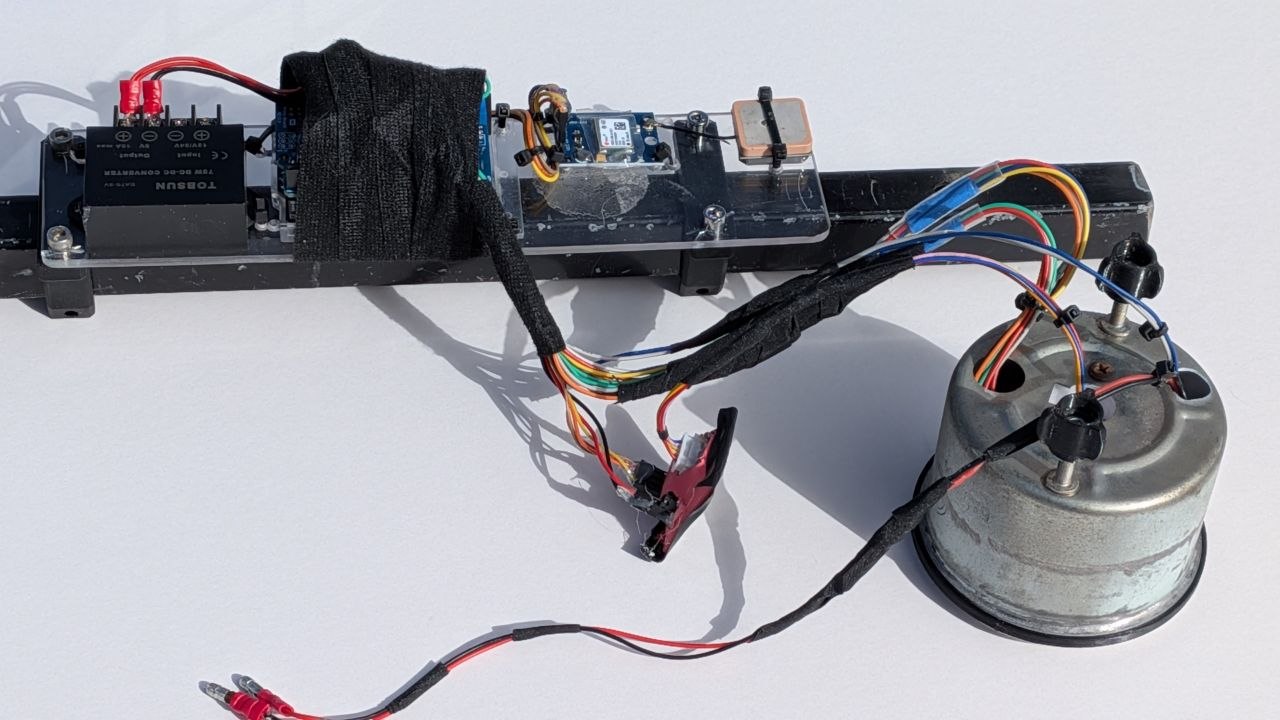
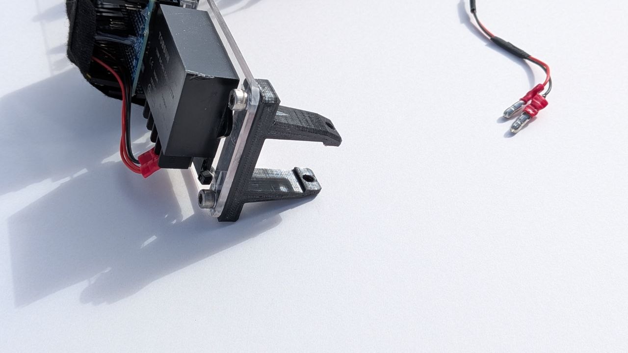
Because the end goal was a one-of-one GPS speedometer, it made no sense to spend more time and money optimizing the packaging with custom printed circuit boards. As long as the stepper motor and the odometer LCD could be mounted in the case, along with backlighting, I was happy. The parts of the system that wouldn’t fit in the case were mounted externally on a separate polycarbonate panel that clamps to a bar behind the dashboard.
Disclaimer: The images and drawings displayed on this website represent how I designed and/or implemented the construction of my car. I am a car hobbyist, not a professional automotive engineer and I am not representing that any images or text on this website are the best or correct way to do anything. The content on this website is only for thought provoking and entertainment purposes. I am not responsible for anything resulting after someone views this content.
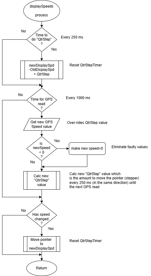
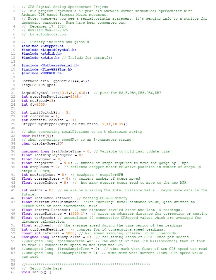
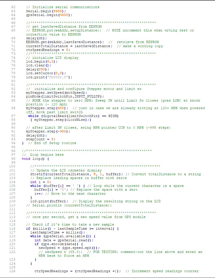
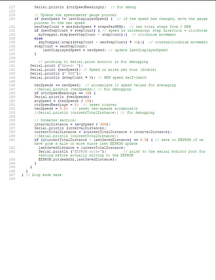
Software:
Next: Making a fiberglass engine cover with a scoop
Back to Content Links for this post


